
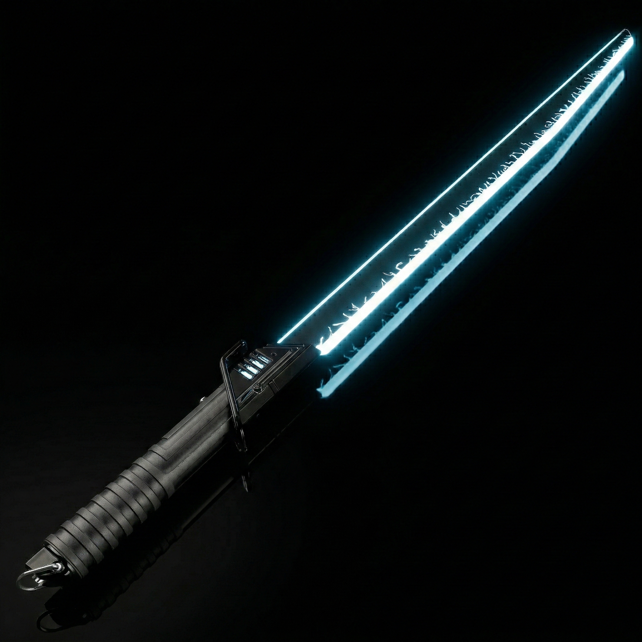
Flat & Katana Lightsaber Blade Technology
Distinct from standard cylindrical lightsabers, to simulate the flat profile of traditional cold weapons (such as Katanas, Tang Swords, or Broadswords), the industry has developed specialized flat-structured pixel blades. Due to physical geometric constraints, their manufacturing processes and component selection differ significantly from round blades.
- Main Body Construction: Physical Limits
Manufacturing a long, hollow, translucent flat blade body is constrained by mold physics to two primary processing routes, with "direct injection molding" of a hollow tube being physically impossible.
Route 1: Extruded Plate + CNC:
The standard for high-end products. Utilizes industrial-grade Extruded Polycarbonate (PC) solid thick plates as the base material.
High-precision CNC machining cuts the outer profile (spine and edge) and mills out the internal cavity for electronics. This preserves the maximum molecular structural strength of the PC material.
Route 2: Injection Molding + Bonding:
Physical Law: It is Impossible to injection mold a single-piece hollow flat PC plate exceeding 70cm in length. The high length-to-thickness ratio causes the flat core to deform under pressure, and extraction (core pulling) becomes impossible after cooling.
Solution: Adopts a "Clamshell Design," molding the left and right halves separately.
Bonding: The halves are then permanently fused via high-strength solvent bonding. This allows for complex surface textures (e.g., fullers).
- Lighting System: 3535 Micro-Pixel Array
Spatial Constraints & Selection: The internal cavity of flat blades is extremely narrow (often just a few millimeters). Standard 5050 LEDs do not fit; thus, the industry standard is the 3535 RGB LED (3.5x3.5mm).
Substrate Selection (FPC vs. PCB):
Full/Dual-Sided Illumination: For designs requiring both spine and edge lighting, Double-sided Rigid PCB Strips are used. The PCB serves as both a circuit carrier and a structural spine.
Single/Edge Illumination: For designs simulating only a cutting edge, Single-sided FPC or Single-sided PCB is selected depending on the curvature requirements.
- Optical Diffusion: Thin Foam & Material Compensation
Physical Dilemma: Due to limited internal space, the Foam layer in flat blades is forced to be extremely thin. Optically, thinner diffusion media means shorter mixing distance, creating a high risk of the "Corn-on-the-cob Effect" (visible individual LED hotspots).
Material Compensation Solution: Since physical distance (foam thickness) cannot be increased, the scattering capability of the medium must be enhanced.
The PC plate must feature a Frosted/Matte Finish or contain high concentrations of Light Diffusion Agents in the raw material.
Logic: Leveraging the high haze of the shell material itself provides secondary diffusion, eliminating granularity and achieving a uniform, neon-like linear glow.
- Electrical Interface: 5-Way Rectangular PCB
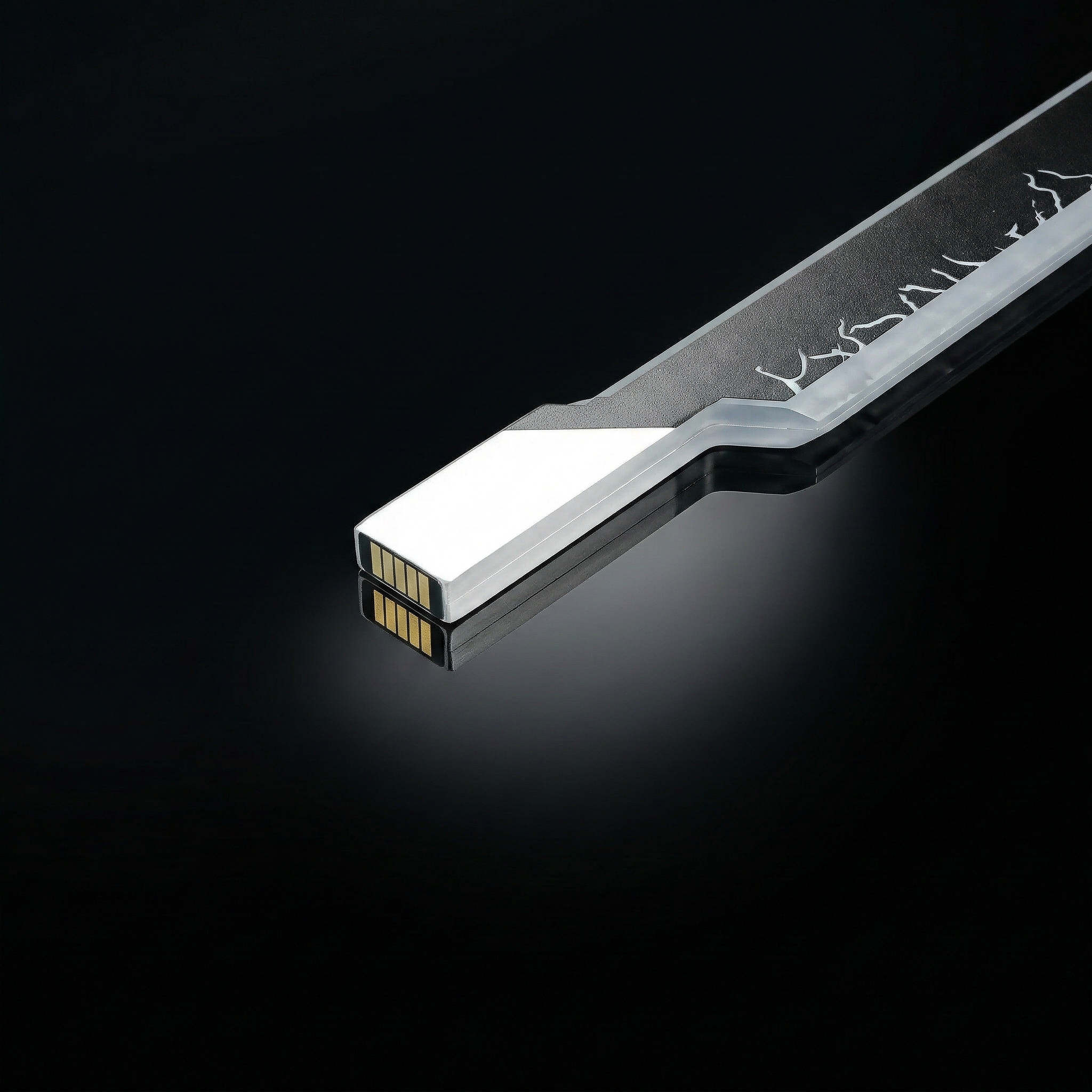
Form Factor Adaptation: Unlike the concentric circular PCBs used in round blades (which possess inherent 360° rotational symmetry), flat blades require a rectangular PCB. This non-circular geometry introduces the issue of "Directionality."
Core Logic of 5-Way Design: Symmetry & Short-Circuit Protection
Limitation of 3-Way: The pixel strip drive requires only 3 physical lines: Positive (V+), Data, and Negative (GND). If designed with only 3 contact pads (e.g., Left-Center-Right), "Reverse Insertion" by the user would cause the V+ pad to contact the GND pin (or vice versa), instantly causing a short circuit and frying the expensive soundboard or battery.
5-Way Fail-Safe Design: The industry-standard 5-Pad Layout is designed not for extra functional channels, but for Electrical Mirrored Symmetry.
Working Principle: The PCB typically employs a symmetric arrangement such as [GND - Data - VCC - Data - GND].
Regardless of whether the user inserts the blade with the "edge facing forward" or "backward," the central VCC always aligns with the power pin, and the parallel-wired Data and GND pads on the sides automatically match their corresponding Pogo Pins.
Conclusion: This is an industrial-grade Safety Redundancy Design. It utilizes 2 extra contacts to eliminate orientation restrictions, completely preventing short circuits caused by user error (reverse installation) and ensuring operational safety.
- Blade Side PCB Chassis
Functional Consistency: The logic here is identical to the chassis in round pixel blades. It is the critical structural component connecting the flat pixel strip to the rectangular PCB.
Structural Role: Must be made of high-strength injection-molded PC. It anchors the PCB and, crucially, clamps the end of the LED strip to prevent displacement during swinging, protecting delicate solder wires from snapping. This is the structural foundation that allows flat blades to be used for active play.
Exotic & Irregular Blade Technology
For other exotic blades appearing on the market (e.g., serrated, spiral), most core components (strips, foam, connection logic) inherit the mature technologies of the round or flat blades described above. Given that current exotic blades are largely non-standardized custom products without new industrial-grade technical barriers, further elaboration is omitted here. In-depth technical analysis will be reserved for future revolutionary irregular blade structures.