System III:Lightsaber Core Connectivity & Illumination
This system handles the transmission of power/data and the generation of light. It is the bridge between the internal electronics and the external user experience.
1. Interface Standards
Blade Pogo Pin PCB (Emitter PCB )
Standard: A circular PCB with spring-loaded pins (Pogo Pins) used to connect the chassis to the Pixel Blade.
Status: This is the absolute Mainstream Standard. It allows for high current transmission and data stability.
Critique: Any manufacturer not using this (e.g., using old-style wired connectors) is using Obsolete Technology.
Blade Socket (Fixed Connector)
Mechanism: Used for older "Removable Core" designs where the core plugs into a fixed socket inside the hilt.
UX Issue: It requires precise Rotational Alignment (Keying) to install.
Verdict: This was found on early high-end sabers and is still used by some lightsaber makers. However, it is Cumbersome and Tedious, testing the user's patience every time they reassemble the saber.
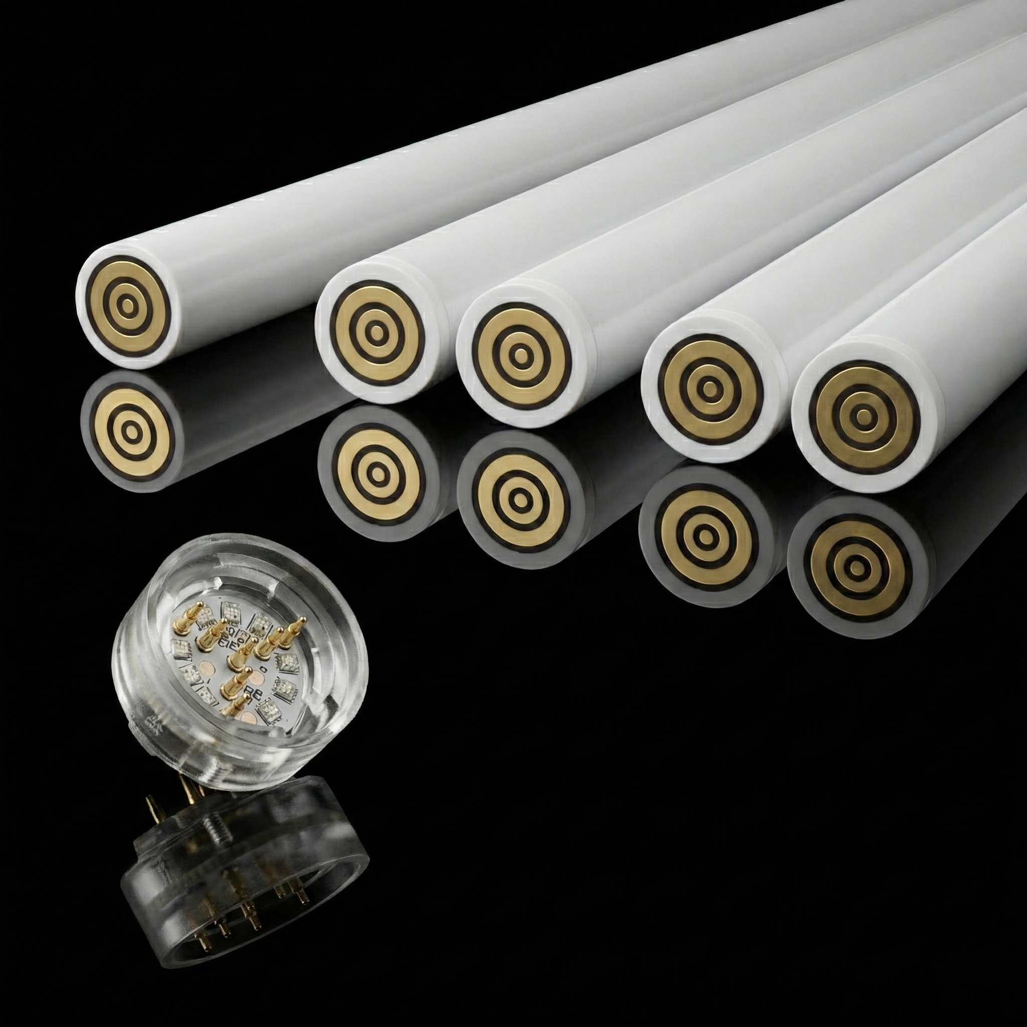
Switch Core Pogo Pin PCB (Chassis-to-Hilt Interface )
Also Known As: "Pogo Pin Core".
Design Logic: It uses a Concentric Ring Contact design (bullseye pattern).
The "Drop-in" Advantage: This is the industry mainstream. Because the rings are 360-degree symmetrical, the user Does Not Need to Align anything. You simply "drop" the core into the hilt, and it connects instantly.
Maintenance: Makes swapping or replacing cores extremely convenient and fast.
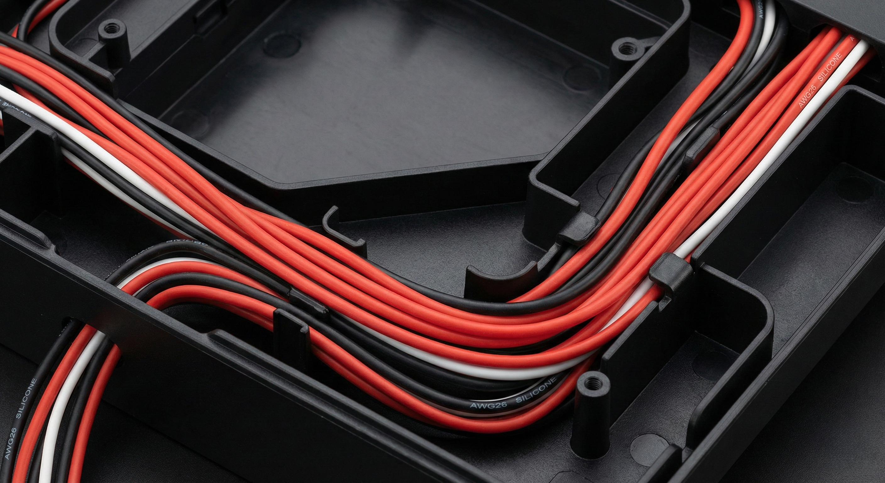
2. Wiring Infrastructure
Specification: High-Temp Silicone Wire (Recommended) vs. PTFE/Teflon Wire.
Why Silicone? Strictly emphasize Soft Silicone Wire.
Flexibility: Silicone wire is ultra-flexible. In a cramped chassis, wires must bend at sharp angles without stressing the solder joints.
Vibration Resistance: During dueling, stiff wires transmit vibration to the solder pads, causing fatigue cracks. Soft silicone absorbs this vibration.
Why NOT PTFE? While PTFE is heat resistant, it is Stiff and Springy. It is hard to route, fights against the assembly, and can spring back, putting tension on delicate components.
3. Illumination Components
- Internal Chassis Aesthetics
Core Accent LEDs: Generally use Color Pixel LEDs (like SK6812 mini) to light up the internal Crystal Chamber.
Pixel Strips (Micro-Detailing):
Spec: Utilize extremely fine 0807 Specification LED strips.
Benefit: These microscopic strips fit into the thin grooves of a detailed chassis without adding bulk, creating futuristic glowing circuit effects.
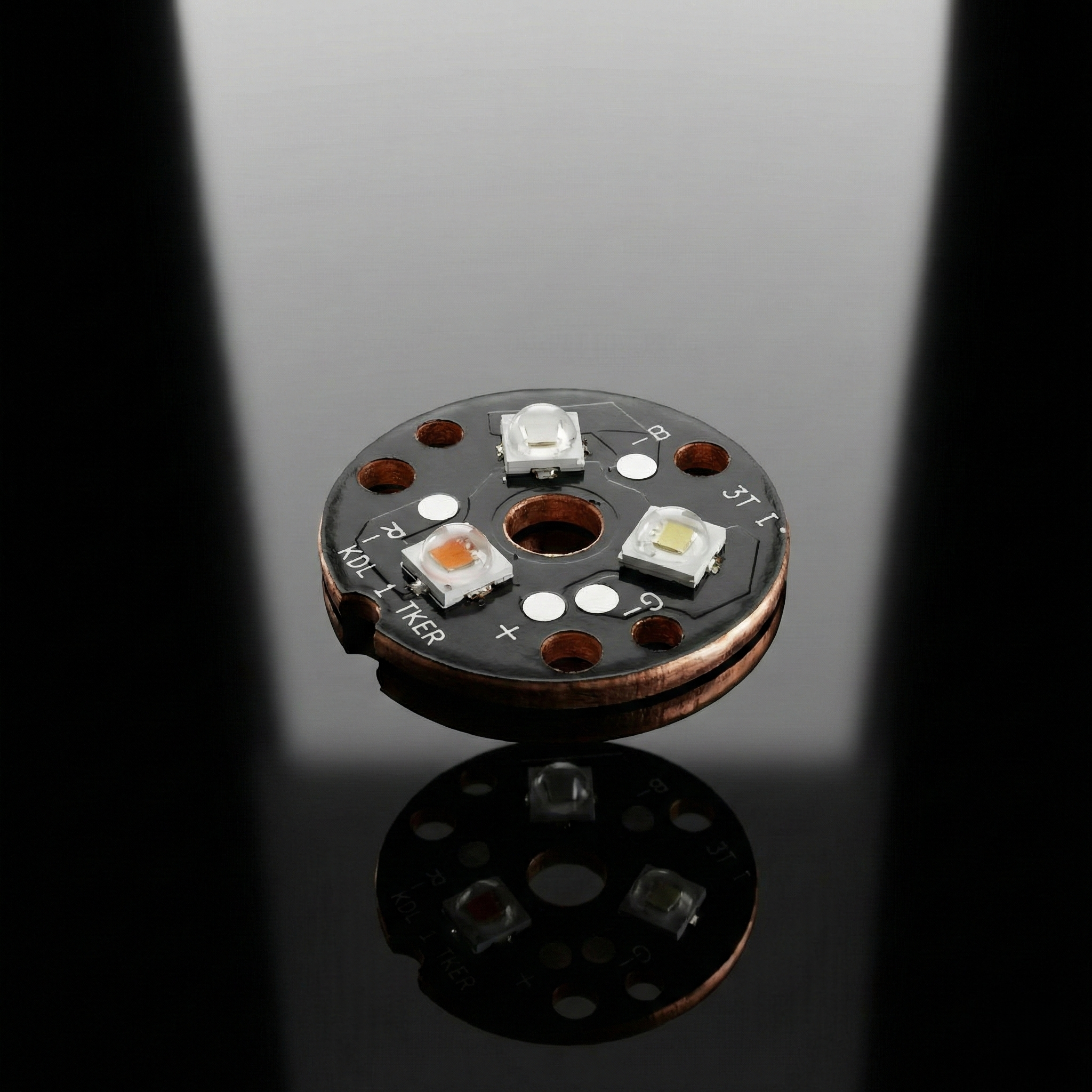
- Main Blade Illumination (Base-lit Only)
Emitter Source: RGB / RGBW LED and RGB Tri-LED.
Tri-LED Advantage: Using a "Tri-Star" (3-die) LED is the professional standard. It is significantly brighter and mixes colors better than single-die cheap LEDs.
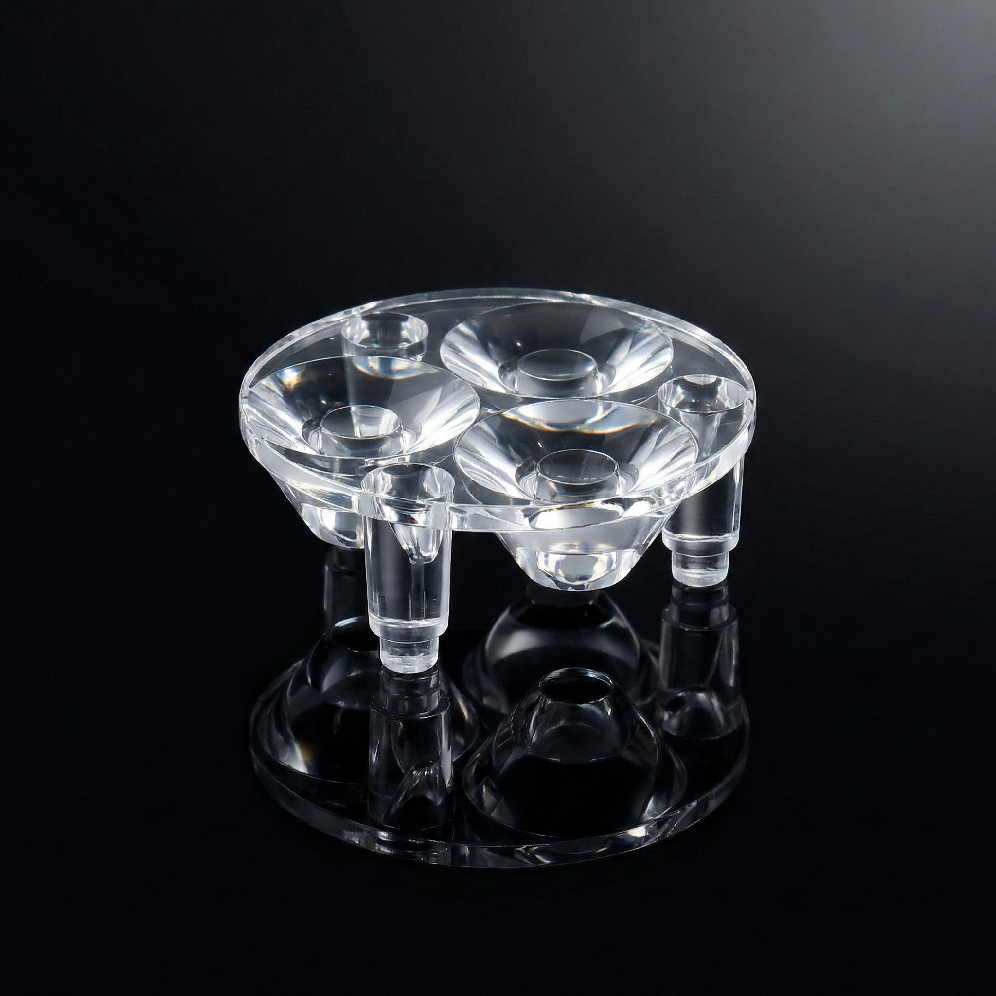
Lens (Optics): Tri-Lens Standard
Necessity: All base-lit LEDs require optical lenses to focus light; without one, the light scatters uselessly.
The Professional Choice: For Tri-LEDs, use a matched Tri-Lens optic. This provides the best possible performance, vastly superior to using generic single lenses on multi-die emitters, by focusing 100% of the combined light output tightly up the blade shaft.
Thermal Management: Heatsink.
High-power Tri-LEDs generate massive heat. A substantial Aluminum or Copper heatsink is mandatory to prevent the LED from burning out.
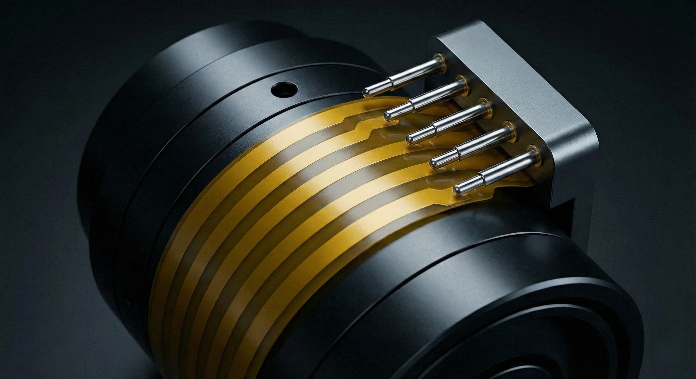
4. Future Innovation: Side Ring FPC Interface
This is a cutting-edge solution for the physical limits of current connectors.
The Bottleneck:
For a standard 1-inch inner diameter hilt, the Switch Core Pogo Pin PCB (end-face connection) has a physical limit of 7 Rings (7 Pins).
If a core needs more functions (e.g., separate data lines for crystal, OLED screen, dual blades), 7 pins are not enough.
The Solution: Side-Wall Contact System (FPC)
Concept: Instead of using the end of the core, we use the side.
Mechanism:
Core Side: A flexible conductive film (Ring FPC) is wrapped around the cylindrical surface of the core. It can support 2, 3, 4, or more distinct conductive tracks (Positive/Negative/Data).
Hilt Side: Spring-loaded pins (Pogo pins) are installed in the inner wall of the hilt.
Operation: When the core slides in, the internal pins press against the side FPC rings.
Advantage: It bypasses the surface area limit of the end cap. It is extremely convenient for assembly and supports complex multi-function cores.