
The Lightsaber Pixel Blade LED System
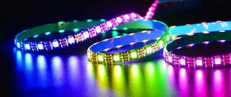
The ability of a Pixel Blade to achieve cinematic scrolling effects and color changing lies in its integrated Programmable LED Array. The manufacturing process of this component directly dictates the blade's brightness, color uniformity, and production efficiency.
1.Substrate Evolution: From FPC to Rigid PCB
Early Process (FPC): Initially, the industry universally adopted Flexible Printed Circuits (FPC).
Drawback: FPC is pliable and difficult to keep straight during assembly into foam tubes, often twisting and causing a "snaking" light effect. Furthermore, its lack of structural rigidity hindered automated assembly.
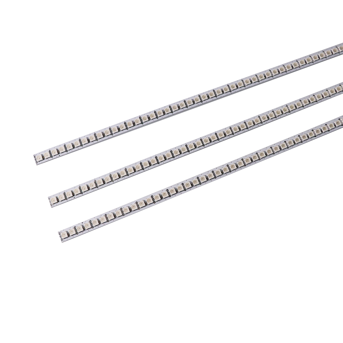
Modern Standard (Rigid PCB): To optimize assembly and enhance structural integrity, the industry has transitioned to customized Long Rigid PCBs.
Advantage: The rigid board acts as a spine, ensuring absolute straightness within the tube. Additionally, the rigid substrate facilitates SMT assembly, significantly reducing defect rates.
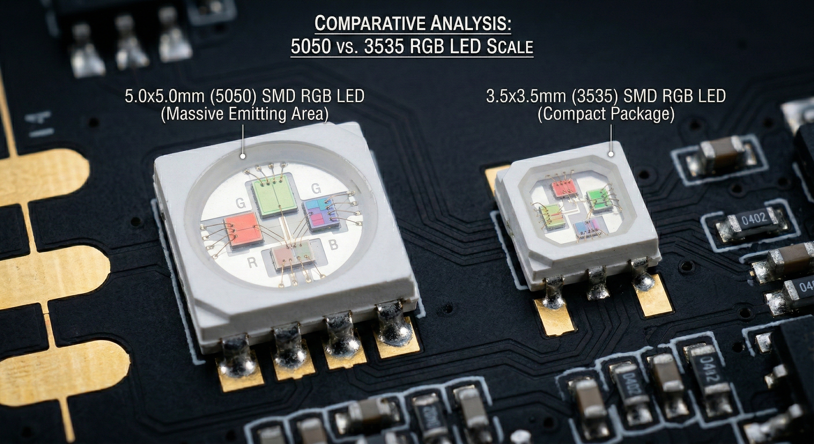
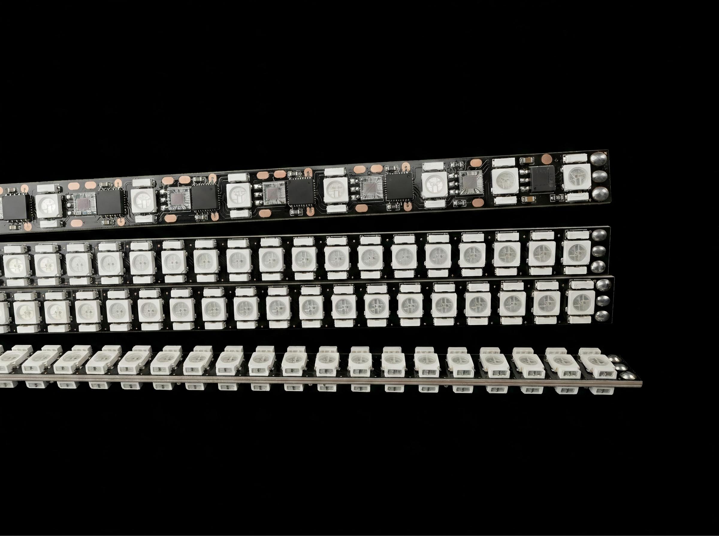
2.Light Source Selection:5050 vs 3535
Mainstream (5050): The industry standard configuration is double-sided, back-to-back mounted 5050 RGB LEDs (5.0x5.0mm).
Physical Logic: The 5050 package features a larger emitting chip area, providing higher Luminous Flux, making it the primary choice for high-brightness blades.
Alternative (3535): While 3535 LEDs (3.5x3.5mm) can be used, their smaller package limits the emitting area. Under the same driving current, the overall brightness of a 3535 strip is generally inferior to that of a 5050 strip. Therefore, unless constrained by ultra-thin tube space, high-end products favor 5050.
3 The Physics Challenge: Voltage Drop & Color Shift
High-Density Load: A standard 1-meter (or 36-inch) pixel blade carries an extremely high density of LEDs.
Data: A 1-meter version typically contains 144 x 2 (288) LEDs; a 36-inch version has approximately 128 x 2 (256) LEDs.
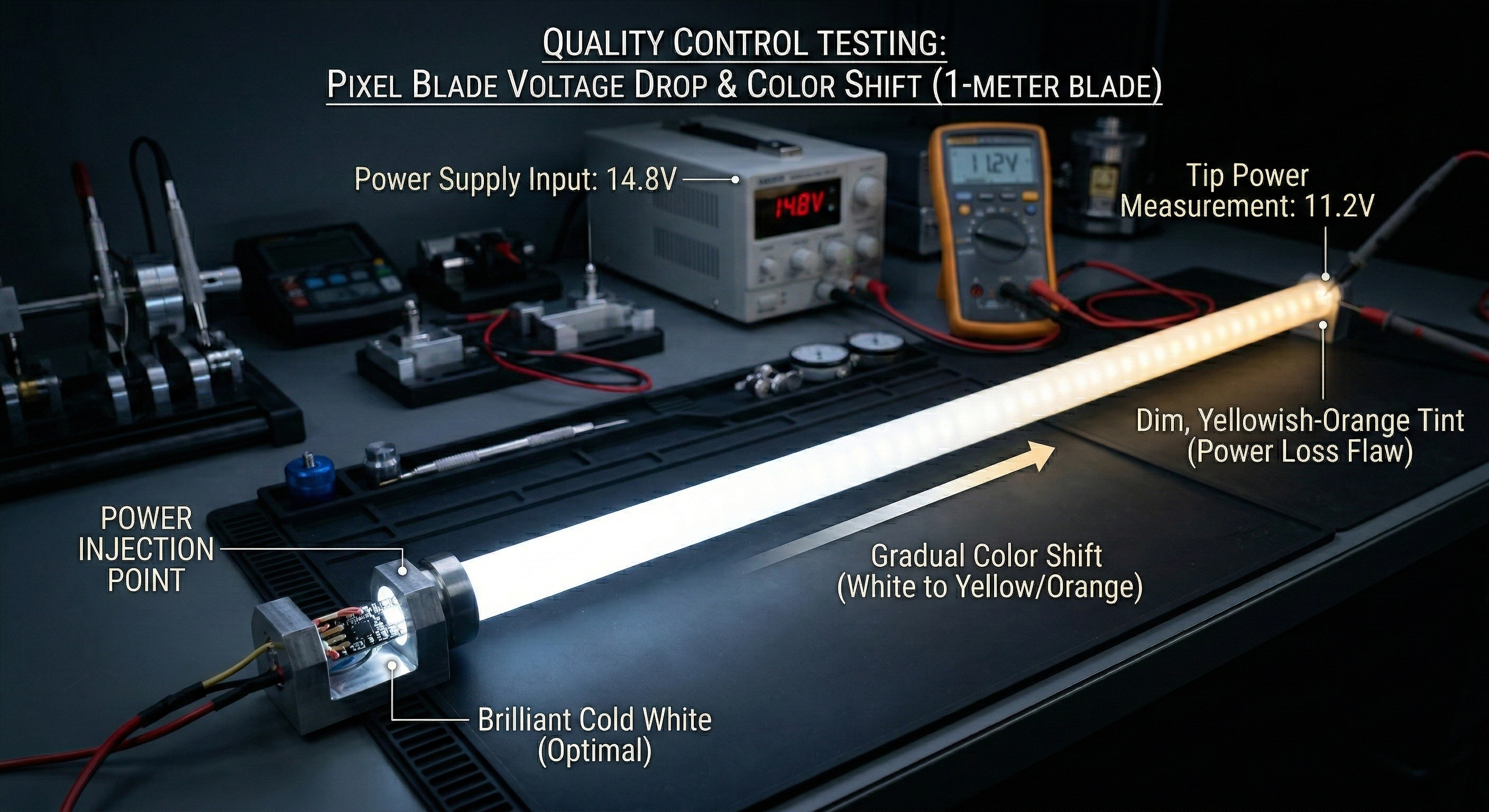
Voltage Drop Phenomenon: According to Ohm's Law, current transmission incurs voltage loss due to trace resistance. When hundreds of LEDs are fully lit (especially in white mode), current can reach 10A-15A.
Color Shift Principle: Voltage drops significantly as current reaches the tip. Since Blue LEDs require the highest forward voltage (~3.0V-3.2V), they dim first when voltage is insufficient, while Red (~2.0V) and Green remain bright. The lack of blue causes the white light at the tip to turn an unsightly Yellow.
Solutions: Power Injection vs. Heavy Copper
Old Method: External Wiring
Process: Manufacturers soldered extra wires (Power Injection Wires) connecting the base directly to the tip to force current delivery.
Flaw: This "physical patch" not only increased soldering labor and reduced efficiency but also created visible Shadowing inside the blade due to the extra wire, severely compromising aesthetics.
Process: Modern high-end manufacturers employ Heavy Copper Traces by increasing the thickness and width of the copper foil within the PCB layers.
Physical Logic: Increasing the conductor cross-section directly reduces trace resistance (R=ρL/A). This allows current to travel efficiently to the tip internally, eliminating the need for external wires.
Cost: While this solves color uniformity issues and boosts aesthetics and efficiency, the manufacturing cost of Heavy Copper Boards (2oz or higher) is significantly higher than standard boards. This is an unavoidable cost for quality.
4.The Ultimate Pursuit: Multi-Sided Illumination & Thermal Management
Multi-Sided Arrays
Trend: To achieve brightness with no blind spots, 4-sided and even 6-sided pixel strips have emerged.
Advantage: Doubling (or tripling) the LED count pushes the lumen output to the extreme, eliminating the slight side shadows found in double-sided strips.
System Challenges
Current Demand: Driving such massive arrays requires immense current. This dictates the saber must be equipped with:
High-Power Soundboard: Featuring MOSFETs capable of handling sustained high currents.
High-Performance Battery: High Drain Li-ion batteries.
Heavy Gauge Wiring: Internal wiring must be sufficiently thick (e.g., 22AWG or thicker) to prevent wire overheating.
Thermal Management Crisis:
Heat Generation: Joule heating (Q=I²Rt). Higher current generates alarming amounts of heat from the PCB and LEDs.
Dissipation Dilemma: The strip is sealed inside thermally insulating PC tubes and foam, creating a harsh thermal environment. Trapped heat leads to accelerated LED degradation or even PCB failure.
Conclusion: Creating the brightest pixel blade is not just about stacking LEDs; it is a balancing act involving Circuit Load Capacity and Thermal Physics.