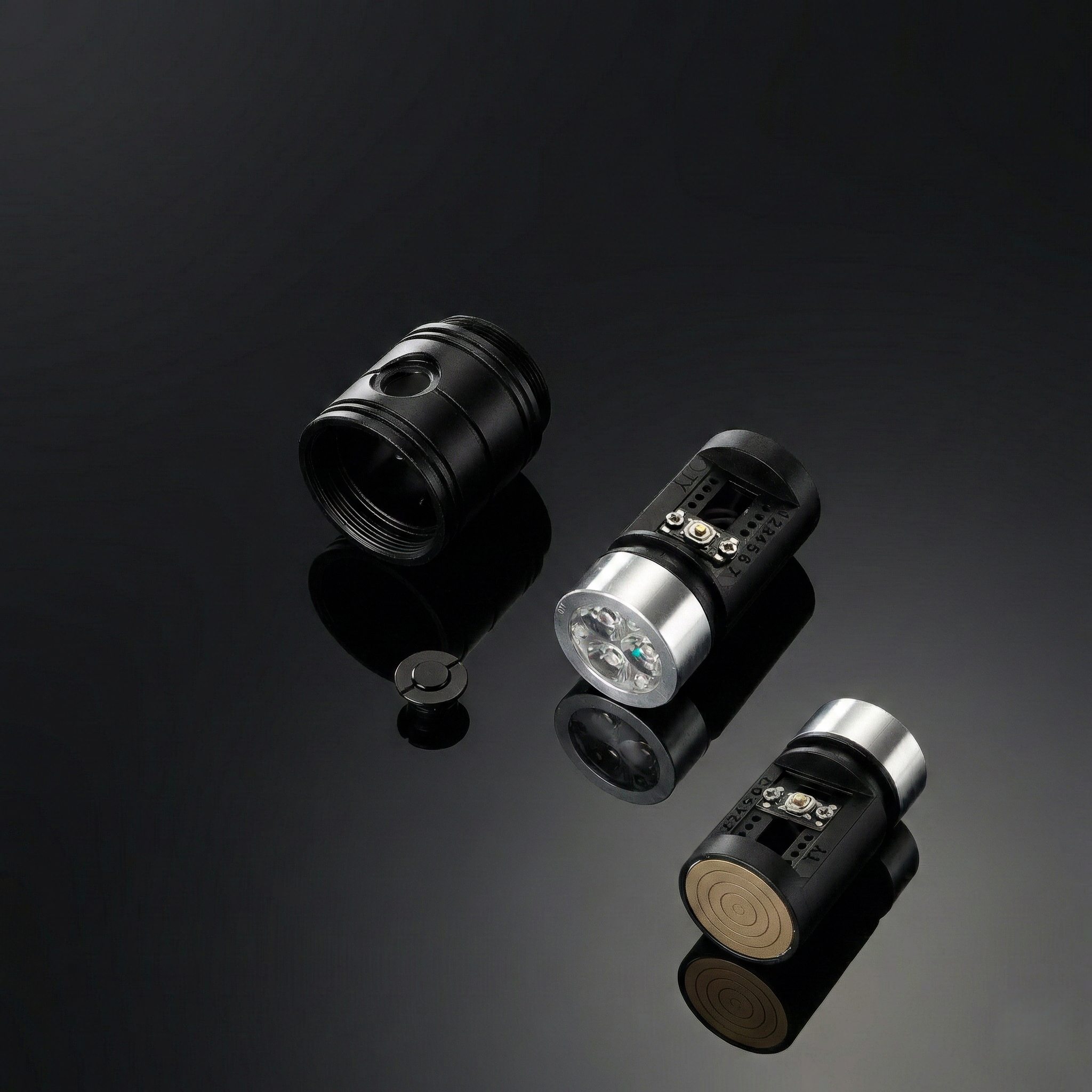
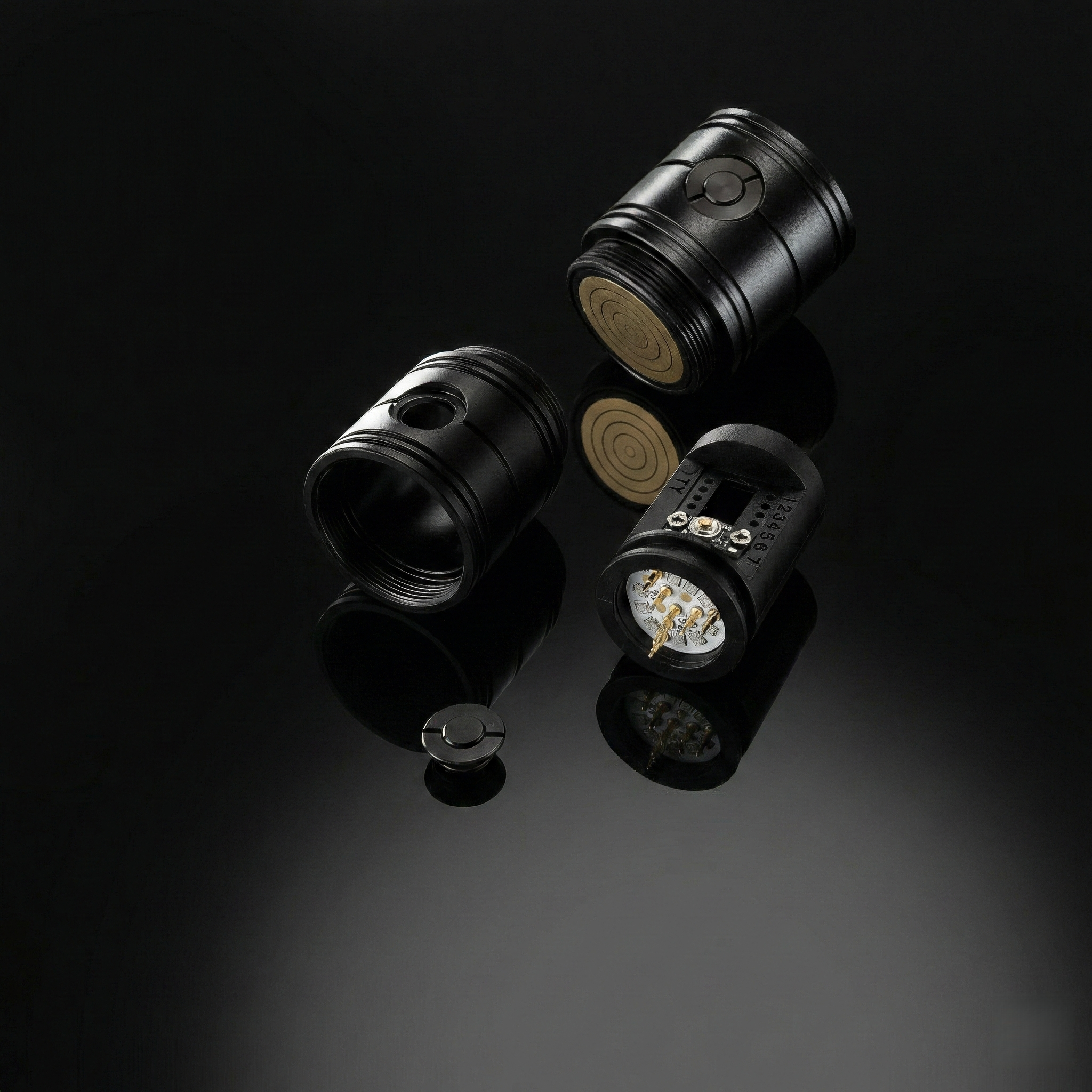
Lightsaber Switch Core Assembly
The Switch Core is the upper control module of a Split Core system. It houses the user interface, blade connectors, and visual feedback systems. It is permanently or semi-permanently installed in the emitter section of the hilt.
1. Switch Chassis (Structural Framework)
The logic here mirrors the Main Chassis.
2. Control Interface: Plunger & PCB
This is the physical bridge between the user's finger and the electronic signal.
Plunger (The Actuator)
Definition: The external metal or plastic cap installed on the hilt. It is not the switch itself, but the mechanical rod that pushes the switch.
Engineering Logic: The Plunger requires precise Tolerance Control. It must float freely in the hilt hole but be long enough to hit the internal Tactile Switch without crushing it.
Switch PCB (The Electronic Trigger)
Standard Component: Tactile Switch (Momentary / Auto-Reset).
Industry Rule: Lightsabers MUST use Momentary Switches.
Why? Soundboards rely on "Long Press," "Double Click," and "Hold" gestures to trigger effects (Lockup, Menu, Volume).
Obsolete Tech: Latching Switches (Self-Locking/Clicky On-Off) are eliminated from the market because they physically cannot send complex signal pulses.
Manufacturing: SMT vs. Manual Soldering
The Old Way: Hand-soldering switches is a nightmare. Switch legs are tiny. Manual soldering leads to "Cold Joints" (weak connection) or melted plastic casings. High defect rate.
The Best Way (SMT): Use STM (Surface Mount Technology) machines to mount the switch directly onto the PCB.
Result: Zero Soldering required for assembly. This guarantees 100% consistency, zero desoldering risks, and extremely low after-sales costs.
3. Visual & Haptic Feedback Modules
Accent LEDs (Button LEDs)
Integration: These are typically SK6812 Mini pixel LEDs soldered directly next to the switch on the same PCB.
Function: They illuminate the Plunger (if translucent) or the chassis window, syncing with the blade color.
Display Screens (OLED / LED Matrix)
The logic here mirrors the Main Chassis.
Motor (Vibration)
The logic here mirrors the Main Chassis.
Crystal Chamber (The Soul)
The logic here mirrors the Main Chassis.
4. High-Power Interconnections
Main Blade Connector (Main Blade Pogo Pin PCB)
Function: The primary power output. Uses heavy-duty Pogo Pins to transmit high current (10A+) to the main pixel blade.
Side Blade Connectors (Crossguard Pogo Pin PCB)
Application: Specifically for Crossguard Sabers (e.g., Kylo Ren style).
Structure: Two smaller Pogo Pin PCBs mounted at 90-degree angles to the main axis.
Challenge: Requires complex wiring routing within the switch chassis to power three blades simultaneously.
Receiver PCB (Split Core Interface)
Definition: The "Bottom" of the Switch Core.
Mechanism: It features a Concentric Ring Contact PCB (Bullseye pattern).
Function: It mates with the Pogo Pins of the Main Battery Core (Lower Chassis). This allows the battery core to be inserted blindly and connect power/data to the buttons and blade instantly without wiring.