Lightsaber Hilt Mechanical Standards & Engineering Specifications
1. Lightsaber Hilt ID Standards & Tolerances
Considering the dimensions of circular blades; there are no fixed standards for irregular-shaped blades. The industry-standard circular blade sizes are 1 inch and 7/8 inch. The hilt's emitter inner diameter (ID) is determined based on these two blade sizes.
Generally, the ID is approximately 0.1mm larger than the blade, specifically between 0.05mm and 0.15mm. If the gap is smaller than this range, the blade will be difficult to insert due to its own manufacturing tolerances. If the gap exceeds this range, the blade will wobble and fail to secure tightly.
"Thin-neck" lightsabers usually require the emitter ID to fit 7/8 inch blades. Due to the limited depth of thin-neck emitters, the 7/8 inch blade is relatively lighter and can be secured firmly; otherwise, it would lead to numerous customer complaints and after-sales issues.
The ID of lightsaber parts other than the emitter is determined by factors such as design aesthetics, speaker size, and chassis dimensions. Generally, keeping the hilt's ID consistent with the emitter's ID facilitates assembly and production. A uniform ID throughout the body makes machining much simpler and significantly reduces costs.
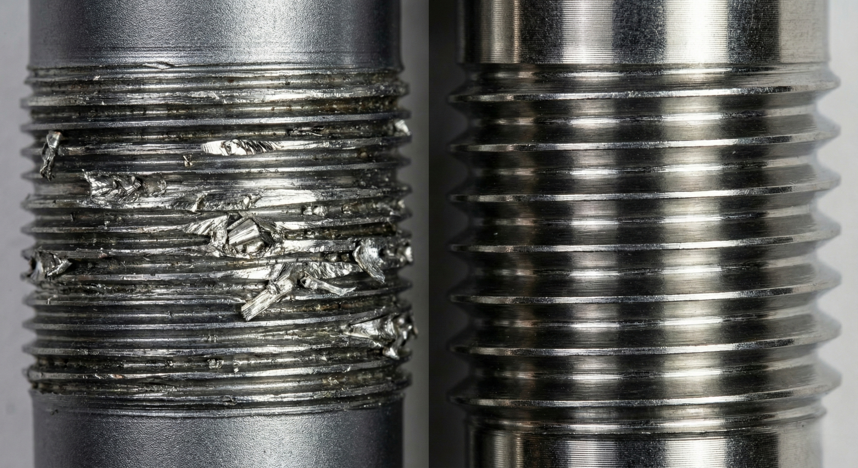
2. Lightsaber Hilt Thread Specifications & Structural Integrity
The three most critical aspects of thread dimensions are thread density, thread depth, and thread thickness.
The thread standard in the lightsaber industry is the VHC system. The massive market volume of the company that established the VHC system, along with the system's ability to support "saber combat" requirements, has solidified its unshakeable status.
Lightsabers with threads below the VHC standard have very low structural strength, making it easy to snap aluminum alloy threads. While aluminum alloy is the common material for lightsabers, other materials like steel are much stronger.
Thread density should not be too high (fine). Overly dense threads are prone to stripping, especially after processes like anodizing or electroplating. Fine threads also make replacing electronic components difficult and assembly cumbersome.
Conversely, overly coarse threads tend to loosen during prolonged use, requiring frequent tightening and affecting the user experience. Thread density can vary based on different finishing processes; for instance, electroplated threads should be coarser to ensure sufficient clearance for the plating material, preventing the gaps from filling up and causing the threads to strip or seize.
If the thread depth is too shallow, the threads are prone to breaking. In special cases, switching to steel can resolve issues caused by shallow thread depth.
If the thread wall is too thin, the threads are likely to fracture. If the ID is fixed, the thread can be thickened by increasing the OD. If the OD is fixed, the thread can be thickened by reducing the ID (as seen in the thin-neck sections). In specific scenarios, using steel is the solution for thin thread walls.
3. Lightsaber Hilt Blade Retention Systems
Blade retention typically utilizes set screws (Retention Screws). The hole positions should not be symmetrical; a triangular hole pattern is generally the most stable. Even if symmetrical holes are drilled, screws should not be applied symmetrically to secure the blade. Securing a blade by pressing it against the inner wall of the hilt is more stable than having screws press against other screws.
For thin-neck lightsabers, due to limited space in the emitter, an extended emitter is often used specifically for blade retention, while the short emitter serves only as a "blade plug" to maintain the lightsaber's accurate proportions.
The most common issue with hidden retention holes is that loose screws can press against the internal hilt sleeve, causing the emitter to seize and making it impossible to secure the blade. To solve this, the screw hole must be recessed inward by several millimeters.
Some combat sabers currently on the market secure the blade without screws, relying instead on a specialized blade-side PCB chassis that locks into the bottom of the emitter. The outer ring of the PCB frame is larger than the blade itself. During assembly, the emitter is first slid over the blade and then screwed onto the hilt. This locks the blade in place without needing screws for pressure, making it more convenient and stable.
4. Lightsaber Hilt Heat Dissipation
For base lit lightsabers, the hilt itself serves as a massive heat sink. To achieve high brightness, the LED module requires high current and high-power LEDs. Relying solely on small heat sinks or thermal adhesive within the internal chassis is insufficient for effective heat dissipation.
This explains why the metal LED module of an base lit lightsaber core becomes extremely hot when not installed in the hilt, and why the plastic chassis components near the LED module can melt.
Once the core is installed into the metal hilt, the hilt acts as the radiator for the LED module. This is why base lit lightsaber hilts feel slightly warm during use. However, this heat is controlled and, with the metal hilt attached, will not cause skin burns.
5. Lightsaber Hilt Acoustic Engineering & Resonance Physics
5.1.Helmholtz Resonance —— The Key to Bass
A lightsaber's resonance chamber is essentially a Helmholtz resonator. Much like blowing across a beer bottle neck creates a "humming" sound, the cavity at the end of the lightsaber amplifies specific sound frequencies.
Physical Principle
f=v/(2π) √(A/(VL))
Where V is the cavity volume, A is the vent area, and L is the vent channel length.
Guidelines for Factories
The distance from the speaker diaphragm surface to the inner wall of the pommel is critical.
For standard 24mm or 28mm speakers, a resonance space of 15mm - 25mm is recommended.
Distance too short (<10mm): The sound becomes "flat" and the treble becomes piercing because low-frequency waves lack the space to form.
Ideal distance (15-25mm): Allows for optimal standing waves, significantly enhancing the depth of the bass.
Distance too long (>40mm): The sound becomes muddy, and volume decreases due to transmission loss.
5.2.Phase Cancellation & Sealing —— The Key to Volume
This is the most common mistake made by factories. When a speaker operates, the cone moves forward to compress air (front wave) while simultaneously creating rarefied air behind it (rear wave). If these two are not isolated, the front and rear waves will mix around the speaker edges, causing phase cancellation.
Physical Phenomenon: Positive Pressure + Negative Pressure = Zero Sound (Bass almost completely disappears).
Guidelines for Factories
The speaker mounting position must be completely airtight. There must be no air leaks between the core and the metal inner wall, or the speaker must be fully sealed with adhesive within the core.
Testing Standard:Instruct the factory: if the sound becomes louder when the vent is blocked after assembly, or if the sound becomes very faint and high-pitched, a "phase short circuit" has occurred, indicating a poor seal.
5.3.Acoustic Impedance & Venting Area
Sound requires airflow to propagate. If the sound vents at the end of the hilt are poorly designed, they will create turbulence, resulting in a "whooshing" wind noise rather than clear audio.
Physical Logic:All sound requires pushing air. If the vents are too small and air cannot be pushed out, the speaker diaphragm becomes "locked" by back pressure, causing a sudden drop in volume.
Guidelines for Factories
Minimum Vent Area Principle:The total area of all vents on the pommel must be at least 20% - 30% of the effective area of the speaker diaphragm.
Hidden Vent Traps:Many replica lightsabers place sound holes on the sides (hidden) to match movie props.Without acoustic calculation, these narrow slits will heavily attenuate high frequencies,leaving only muffled bass. If hidden vents are necessary, the total airflow must be guaranteed by increasing the number of slits.
5.4.Material Acoustic Reflection
Harder Materials are Better:6061Aluminum has a better acoustic reflection rate than plastic.
Inner Wall Treatment:Smooth metal inner walls assist in sound reflection but may also create standing waves that cause piercing sounds.
Advanced Design for High-end Factories:Faint threads or textures can be designed on the inner walls of the resonance chamber. This helps break up high-frequency standing waves, making the sound "purer" and reducing metallic harshness.)
5.5.Core Physical Difference: Perimeter-to-Area Ratio
When sound passes through a hole, it is not just wave propagation; it is accompanied by rapid air movement (especially at high volumes and strong low-frequency vibrations).
Round Holes
Physical Properties:The circle has the smallest perimeter-to-area ratio. This means for the same opening area, a round hole has the least edge friction.
Acoustic Performance:The airflow is smoothest with minimal turbulence. The sound is punchy and solid. The bass impact is stronger because the air column is pushed out in a more concentrated manner.
Slots
Physical Properties:For the same area, slots have longer perimeters. Air moving through long edges generates more edge friction.
Acoustic Performance:If slots are too narrow (width < 2mm), they can easily produce a "wind whistle" or "hissing" sound (similar to the principle of whistling). This can contaminate the lightsaber's original Hum, making the sound "dirty." However, the advantage is that radial slot designs can often achieve a larger total opening area on a limited pommel diameter, thereby increasing overall loudness.
Frequency Response
Bass:Low-frequency wavelengths are very long (decimeters to meters), making them insensitive to hole shape. As long as the total area is sufficient, there is little difference in bass between round holes and slots.
Treble:High-frequency wavelengths are short and directional. Round holes tend to form more concentrated high-frequency beams. Slots or meshes cause more complex diffraction, which may improve sound diffusion but, if edges are sharp, can cut out some high-frequency detail.
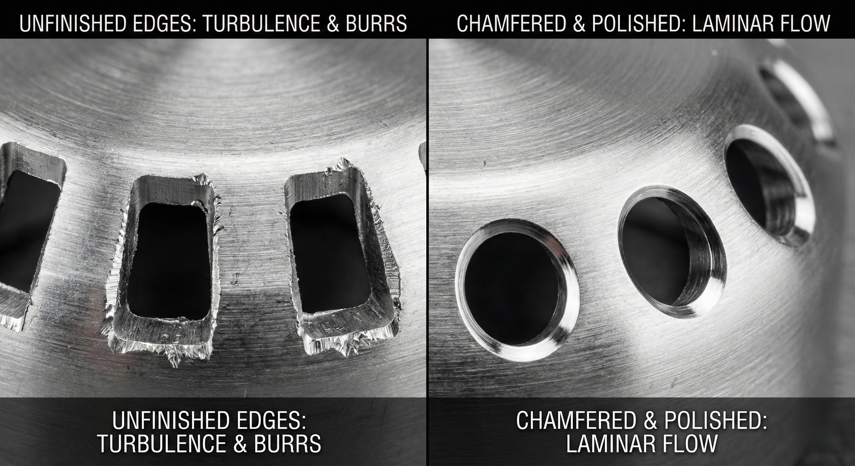
The "Secret Sauce" for Manufacturing
Chamfering/Deburring —— The Critical Step:Whether round holes or slots, CNC-machined edges are usually right-angled (90 degrees). Sharp edges cut through fast-moving air like a blade, creating high-frequency turbulence noise. Instruct the factory to perform chamfering or filleting on both the interior and exterior of all sound vents. Smooth edges allow air to enter and exit in a laminar flow, reducing noise and making the swing sound effects purer.
Minimum Width Rule for Slots:If slots are necessary for aesthetics, a minimum width of 2.5mm is recommended. Narrow gaps (e.g., 1mm) act as a whistle under high sound pressure, obstructing sound and creating strange high-frequency noise.
Honeycomb Effect for Mesh Designs:For multi-hole designs, the web thickness between holes should be as thin as possible while maintaining structural integrity. Reason: This reduces the probability of sound waves bouncing off metal walls back into the cavity, improving acoustic transparency.